The mostly goal in this article is to show how to soldering a JTAG connector in the Beaglebone Black (BBB) board, then in the next post I hope to show you how to connect it with J-Link Segger 8.08.90, at least if it works :). Otherwise, at least you can see here the pinout related to P2 connector in BBB.

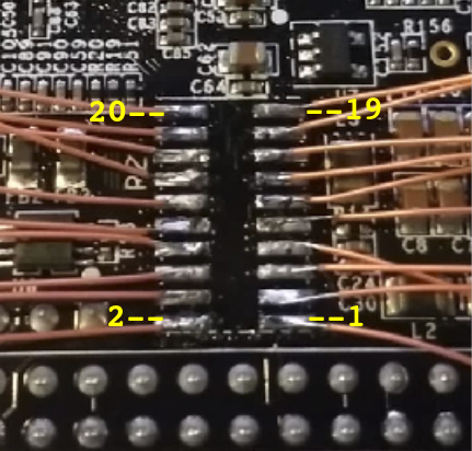
To execute this job I am using a wire-rapping 32 AWG, the final work in the board you can see in the next image. Note that the P2 mark in BBB is in the left side, it means that the schematic is inverted with the board image.

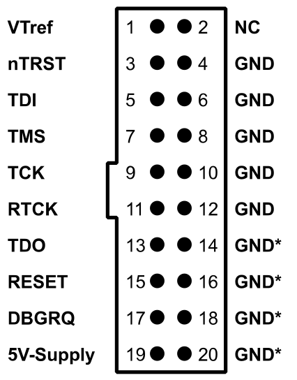
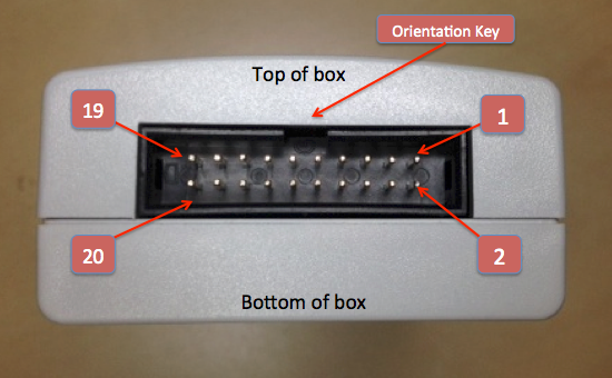
Regarding the connector in J-Link probe, you can see the pinout below and is very important to say that the reference for the pinout is not the cable, but the probe box. At the first time that I soldered the wires it not worked because I took as reference the cable.
Below you can see the final results:
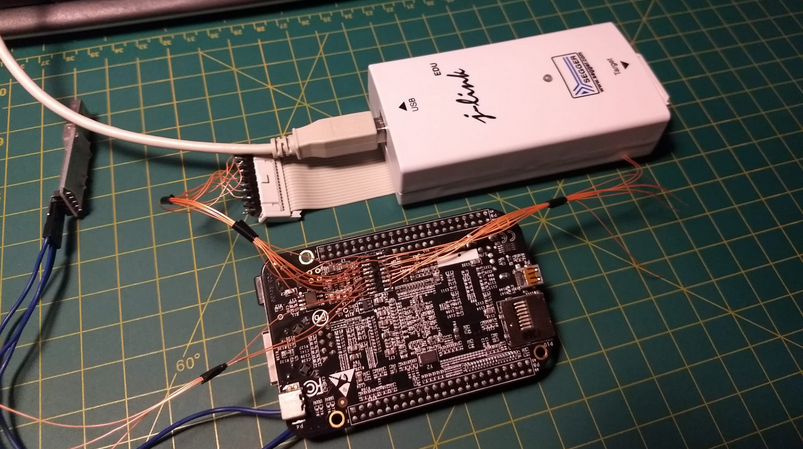
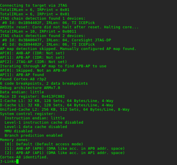
And the success to connect the J-Link to the target, in the BBB the target is a TI (Texas Instruments) AM3359 - ARM Cortex-A8.