This post brings more details about the execution of P4Runtime Basics Tutorial that is part of the Next Generation SDN Tutorial. This post will cover the following topics:
- Look at the P4 starter code
- Compile it for the BMv2 software switch and understand the output (P4Info and BMv2 JSON files)
- Start Mininet with a 2x2 topology of stratum_bmv2 switches
- Use the P4Runtime Shell to manually insert table entries in one of the switches to provide connectivity between hosts
1. Look at the P4 program
To get started, let’s have a look a the P4 program: p4src/main.p4
In the rest of the exercises, you will be asked to build a leaf-spine data center fabric based on IPv6. To make things easier, we provide a starter P4 program which contains:
-
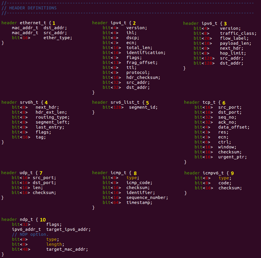
Header definitions
-
Parser implementation
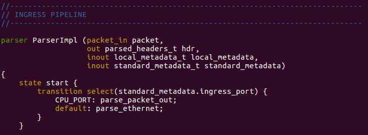 There are more states in the parser implementation, see the code.
 -
Ingress and egress pipeline implementation (incomplete)
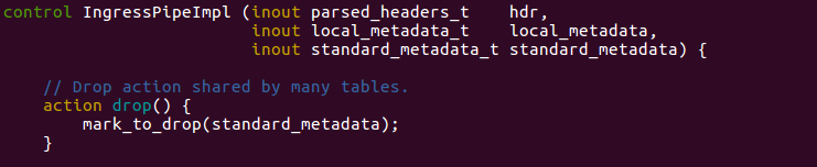
 See the ingress and the egress pipeline implementation for more details.
 -
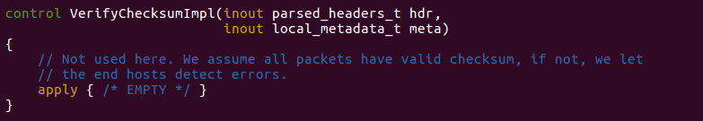
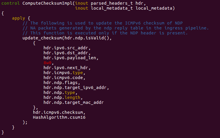
Checksum verification/update
The implementation already provides logic for L2 bridging and ACL behaviors. We suggest you start by taking a quick look at the whole program to understand its structure. When you’re done, try answering the following questions, while referring to the P4 program to understand the different parts in more details.
Parser
- List all the protocol headers that can be extracted from a packet.
- ethernet
- ipv4
- ipv6
- srv6h
- srv6_list
- tcp
- udp
- icmp
- icmpv6
- ndp
- Which header is expected to be the first one when parsing a new packet
- The first one will be the ethernet header, in the parser implementation it is in the “start” state.
Ingress pipeline
- For the L2 bridging case, which table is used to replicate NDP requests to all host-facing ports? What type of match is used in that table?
- The l2_ternary_table is used to replicate NDP requests to all host-facing ports, to do that the ternary match is used.
- In the ACL table, what’s the difference between send_to_cpu and clone_to_cpu actions?
- TBD
- In the apply block, what is the first table applied to a packet? Are P4Runtime packet-out treated differently?
- The first table applied is the l2_exact_table. Yes, first it need to be validated.
Egress pipeline
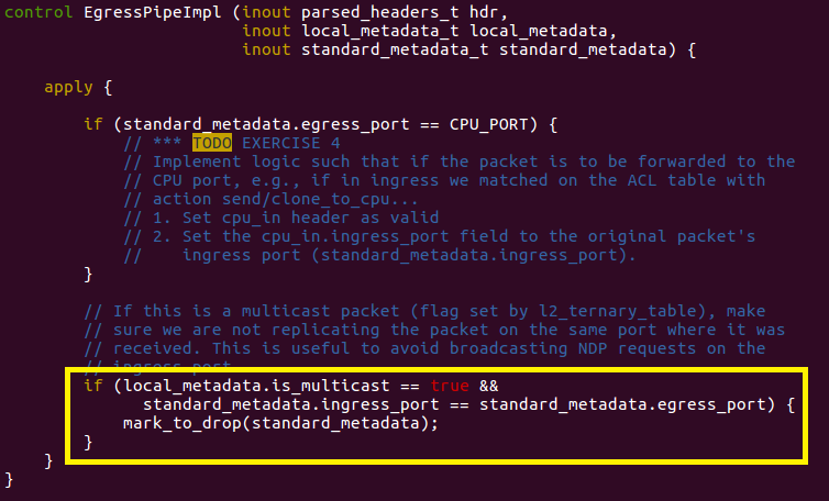
- For multicast packets, can they be replicated to the ingress port?
- No, it cannot be replicated and if it is a multicast packet then it is droped. See below:
Deparser
- What is the first header to be serialized on the wire and in which case?
- The first header is the cpu_in_header and there is no condition for that, it will happen always.
2. Compile P4 program
The next step is to compile the P4 program for the BMv2 simple_switch target. For this, we will use the open source P4_16 compiler (p4c) which includes a backend for this specific target, named p4c-bm2-ss.
To compile the program, open a terminal window in the exercise VM and type the following command:
make p4-build
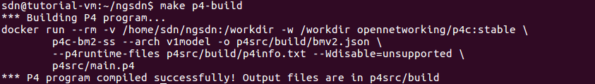
You should see the following output:
*** Building P4 program...
docker run --rm -v /home/sdn/ngsdn-tutorial:/workdir -w /workdir
 opennetworking/p4c:stable \
                p4c-bm2-ss --arch v1model -o p4src/build/bmv2.json \
                --p4runtime-files p4src/build/p4info.txt --Wdisable=unsupported \
                p4src/main.p4
*** P4 program compiled successfully! Output files are in p4src/build
We have instrumented the Makefile to use a containerized version of the p4c-bm2-ss compiler. If you look at the arguments when calling p4c-bm2-ss, you will notice that we are asking the compiler to:
- Compile for the v1model architecture (
--archargument); - Put the main output in
p4src/build/bmv2.json(-o); - Generate a P4Info file in p4src/build/p4info.txt (
--p4runtime-files); - Ignore some warnings about unsupported features (
--Wdisable=unsupported). It’s ok to ignore such warnings here, as they are generated because of a bug in p4c.
Compiler output
This file defines a configuration for the BMv2 simple_switch target in JSON format. When simple_switch receives a new packet, it uses this configuration to process the packet in a way that is consistent with the P4 program.
This is quite a big file, but don’t worry, there’s no need to understand its content for the sake of this exercise. If you want to learn more, a specification of the BMv2 JSON format is provided here: https://github.com/p4lang/behavioral-model/blob/master/docs/JSON_format.md
This file contains an instance of a P4Info schema for our P4 program, expressed using the Protobuf Text format.
Take a look at this file and try to answer the following questions:
- What is the fully qualified name of the l2_exact_table? What is its numeric ID?
IngressPipeImpl.l2_exact_table
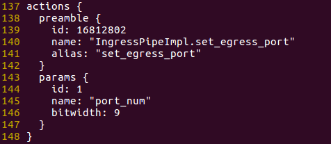
- To which P4 entity does the ID 16812802 belong to? A table, an action, or something else? What is the corresponding fully qualified name?
- It belongs to the
egress_portentity and it is associated to an action. Its fully qualified name isIngressPipeImpl.set_egress_port.
- It belongs to the
- For the IngressPipeImpl.set_egress_port action, how many parameters are defined for this action? What is the bitwidth of the parameter named port_num?
- Only one parameter is defined for this action and its bitwidth is 9.
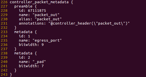
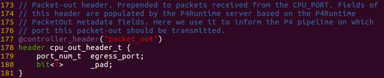
- At the end of the file, look for the definition of the controller_packet_metadata message with name packet_out at the end of the file. Now look at the definition of header cpu_out_header_t in the P4 program. Do you see any relationship between the two?
- Yes, the controller_packet_metadata has two metadatas as the same way we can see in the definition of the header cpu_out_header_t. See the following images:
3. Start Mininet topology
It’s now time to start an emulated network of stratum_bmv2 switches. We will program one of the switches using the compiler output obtained in the previous step.
To start the topology, use the following command:
make start
This command will start two Docker containers, one for mininet and one for ONOS. You can ignore the ONOS one for now, we will use that in exercises 3 and 4.
To make sure the container is started without errors, you can use the make mn-log command to show the Mininet log. Verify that you see the following output (press Ctrl-C to exit):
$ make mn-log
docker-compose logs -f mininet
Attaching to mininet
mininet    | *** Error setting resource limits. Mininet's performance may be affected.
mininet    | *** Creating network
mininet    | *** Adding hosts:
mininet    | h1a h1b h1c h2 h3 h4
mininet    | *** Adding switches:
mininet    | leaf1 leaf2 spine1 spine2
mininet    | *** Adding links:
mininet    | (h1a, leaf1) (h1b, leaf1) (h1c, leaf1) (h2, leaf1) (h3, leaf2) (h4, leaf2) (spine1, leaf1) (spine1, leaf2) (spine2, leaf1) (spine2, leaf2)
mininet    | *** Configuring hosts
mininet    | h1a h1b h1c h2 h3 h4
mininet    | *** Starting controller
mininet    |
mininet    | *** Starting 4 switches
mininet    | leaf1 stratum_bmv2 @ 50001
mininet    | leaf2 stratum_bmv2 @ 50002
mininet    | spine1 stratum_bmv2 @ 50003
mininet    | spine2 stratum_bmv2 @ 50004
mininet    |
mininet    | *** Starting CLI:
You can ignore the “*** Error setting resource limits…”.
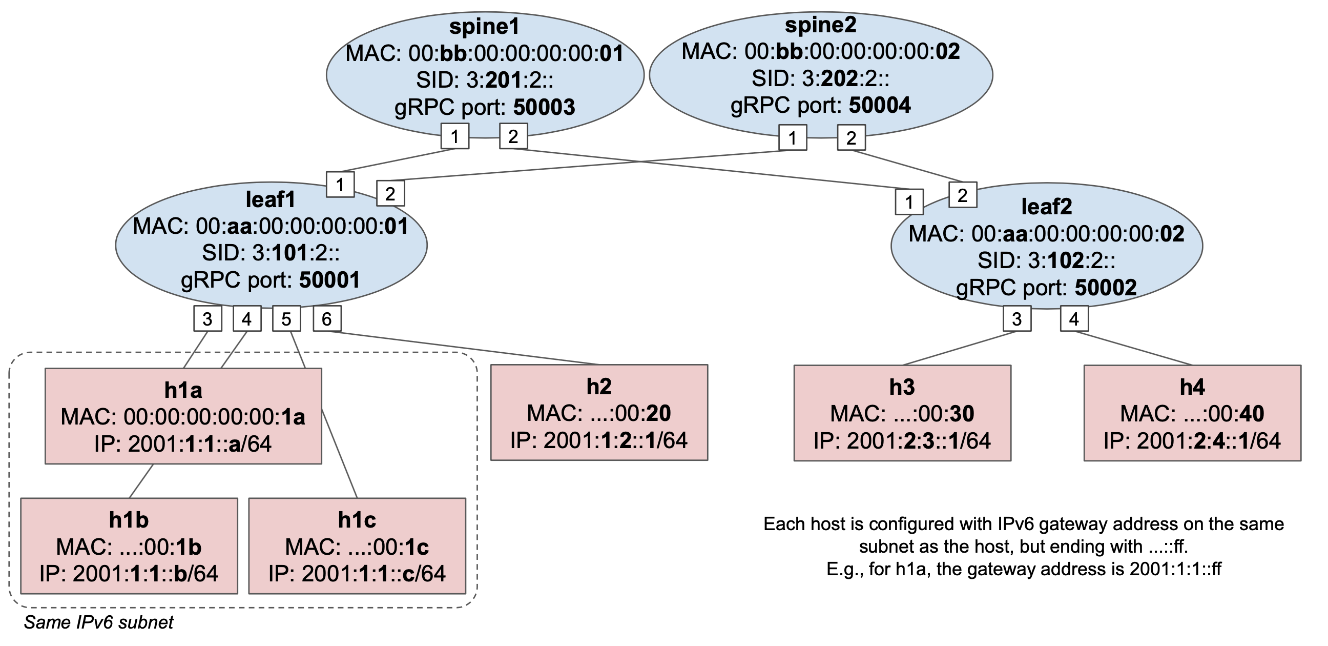
The parameters to start the mininet container are specified in docker-compose.yml. The container is configured to execute the topology script defined in mininet/topo-v6.py.
The topology includes 4 switches, arranged in a 2x2 fabric topology, as well as 6 hosts attached to leaf switches. 3 hosts h1a, h1b, and h1c, are configured to be part of the same IPv6 subnet. In the next step you will be asked to use P4Runtime to insert table entries to be able to ping between two hosts of this subnet.
stratum_bmv2 temporary files
When starting the Mininet container, a set of files related to the execution of each stratum_bmv2 instance is generated in the tmpdirectory. Examples include:
- tmp/leaf1/stratum_bmv2.log: contains the stratum_bmv2 log for switch
leaf1; - tmp/leaf1/chassis-config.txt: the Stratum “chassis config” file used to specify the initial port configuration to use at switch startup; This file is automatically generated by the
StratumBmv2Switchclass invoked by mininet/topo-v6.py. tmp/leaf1/write-reqs.txt: a log of all P4Runtime write requests processed by the switch (the file might not exist if the switch has not received any write request).
4. Program leaf1 using P4Runtime
For this part we will use the P4Runtime Shell, an interactive Python CLI that can be used to connect to a P4Runtime server and can run P4Runtime commands. For example, it can be used to create, read, update, and delete flow table entries.
The shell can be started in two modes, with or without a P4 pipeline config. In the first case, the shell will take care of pushing the given pipeline config to the switch using the P4Runtime SetPipelineConfig RPC. In the second case, the shell will try to retrieve the P4Info that is currently configured in the switch.
In both cases, the shell makes use of the P4Info file to:
- allow specifying runtime entities such as table entries using P4Info names rather then numeric IDs (much easier to remember and read);
- provide autocompletion;
- validate the CLI commands.
Finally, when connecting to a P4Runtime server, the specification mandates that we provide a mastership election ID to be able to write state, such as the pipeline config and table entries.
To connect the P4Runtime Shell to leaf1 and push the pipeline configuration obtained before, use the following command:
util/p4rt-sh --grpc-addr localhost:50001 --config p4src/build/p4info.txt,p4src/build/bmv2.json --election-id 0,1
util/p4rt-sh is a simple Python script that invokes the P4Runtime Shell Docker container with the given arguments. For a list of arguments you can type util/p4rt-sh --help.
Note: we use --grpc-addr localhost:50001 as the Mininet container is executed locally, and 50001 is the TCP port associated to the gRPC server exposed by leaf1.
If the shell started successfully, you should see the following output:
*** Connecting to P4Runtime server at host.docker.internal:50001 ...
*** Welcome to the IPython shell for P4Runtime ***
P4Runtime sh >>>
Available commands
Use commands like tables, actions, action_profiles, counters, direct_counters, and other named after the P4Info message fields, to query information about P4Info objects.
Commands such as table_entry, action_profile_member, action_profile_group, counter_entry, direct_counter_entry, meter_entry, direct_meter_entry, multicast_group_entry, and clone_session_entry, can be used to read/write the corresponding P4Runtime entities.
Type the command name followed by ? for information on each command, e.g. table_entry?.
For more information on P4Runtime Shell, check the official documentation at: https://github.com/p4lang/p4runtime-shell
The shell supports autocompletion when pressing tab. For example:
tables["IngressPipeImpl.<tab>
will show all tables defined inside the IngressPipeImpl block.
Bridging connectivity test
Use the following steps to verify connectivity on leaf1 after inserting the required P4Runtime table entries. For this part, you will need to use the Mininet CLI.
On a new terminal window, attach to the Mininet CLI using make mn-cli.
You should see the following output:
*** Attaching to Mininet CLI...
*** To detach press Ctrl-D (Mininet will keep running)
mininet>
Insert static NDP entries
To be able to ping two IPv6 hosts in the same subnet, first, the hosts need to resolve their respective MAC address using the Neighbor Discovery Protocol (NDP). This is equivalent to ARP in IPv4 networks. For example, when trying to ping h1b from h1a, h1a will first generate an NDP Neighbor Solicitation (NS) message to resolve the MAC address of h1b. Once h1b receives the NDP NS message, it should reply with an NDP Neighbor Advertisement (NA) with its own MAC address. Now both host are aware of each other MAC address and the ping packets can be exchanged.
As you might have noted by looking at the P4 program before, the switch should be able to handle NDP packets if correctly programmed using P4Runtime (see l2_ternary_table), however, to keep things simple for now, let’s insert two static NDP entries in our hosts.
Add an NDP entry to h1a, mapping h1b’s IPv6 address (2001:1:1::b) to its MAC address (00:00:00:00:00:1B):
mininet> h1a ip -6 neigh replace 2001:1:1::B lladdr 00:00:00:00:00:1B dev h1a-eth0
And vice versa, add an NDP entry to h1b to resolve h1a’s address:
mininet> h1b ip -6 neigh replace 2001:1:1::A lladdr 00:00:00:00:00:1A dev h1b-eth0
Start ping
Start a ping between h1a and h1b. It should not work as we have not inserted any P4Runtime table entry for forward these packets.
mininet> h1a ping h1b
You should see no output form the ping command. You can leave that command running for now.
Insert P4Runtime table entries
To be able to forward ping packets, we need to add two table entries on l2_exact_table in leaf1 – one that matches on destination MAC address of h1b and forwards traffic to port 4 (where h1b is attached), and vice versa (h1a is attached to port 3).
Let’s use the P4Runtime shell to create and insert such entries. Looking at the P4Info file, use the commands below to insert the following two entries in the l2_exact_table:
| Match (Ethernet dest) | | | Egress port number |
|---|---|
| 00:00:00:00:00:1B | 4 |
| 00:00:00:00:00:1A | 3 |
To create a table entry object:
P4Runtime sh >>> te = table_entry["P4INFO-TABLE-NAME"](action = "<P4INFO-ACTION-NAME>")
- te = table_entry[“IngressPipeImpl.l2_exact_table”](action = “IngressPipeImpl.set_egress_port”)
Make sure to use the fully qualified name for each entity, e.g. IngressPipeImpl.l2_exact_table, IngressPipeImpl.set_egress_port, etc.
To specify a match field:
P4Runtime sh >>> te.match["P4INFO-MATCH-FIELD-NAME"] = ("VALUE")
- te.match[“hdr.ethernet.dst_addr”] = (“00:00:00:00:00:1B”)
- te.match[“hdr.ethernet.dst_addr”] = (“00:00:00:00:00:1A”)
VALUE can be a MAC address expressed in Colon-Hexadecimal notation (e.g., 00:11:22:AA:BB:CC), or IP address in dot notation, or an arbitrary string. Based on the information contained in the P4Info, P4Runtime shell will internally convert that value to a Protobuf byte string.
The specify the values for the table entry action parameters:
P4Runtime sh >>> te.action["P4INFO-ACTION-PARAM-NAME"] = ("VALUE")
- te.action[“port_num”] = (“4”)
- te.action[“port_num”] = (“3”)
You can show the table entry object in Protobuf Text format, using the print command:
P4Runtime sh >>> print(te)
The shell internally takes care of populating the fields of the corresponding Protobuf message by using the content of the P4Info file.
To insert the entry (this will issue a P4Runtime Write RPC to the switch):
P4Runtime sh >>> te.insert()
To read table entries from the switch (this will issue a P4Runtime Read RPC):
P4Runtime sh >>> for te in table_entry["P4INFO-TABLE-NAME"].read():
            ...:     print(te)
            ...:
After inserting the two entries, ping should work. Go pack to the Mininet CLI terminal with the ping command running and verify that you see an output similar to this:
mininet> h1a ping h1b
PING 2001:1:1::b(2001:1:1::b) 56 data bytes
64 bytes from 2001:1:1::b: icmp_seq=956 ttl=64 time=1.65 ms
64 bytes from 2001:1:1::b: icmp_seq=957 ttl=64 time=1.28 ms
64 bytes from 2001:1:1::b: icmp_seq=958 ttl=64 time=1.69 ms
...
Command sequence:
P4Runtime sh >>> te = table_entry["IngressPipeImpl.l2_exact_table"](action = "IngressPipeImpl.set_egress_port")
P4Runtime sh >>> te.match["hdr.ethernet.dst_addr"] = ("00:00:00:00:00:1B")
P4Runtime sh >>> te.action["port_num"] = ("4")
P4Runtime sh >>> print(te)
P4Runtime sh >>> te.insert()
P4Runtime sh >>> te.match["hdr.ethernet.dst_addr"] = ("00:00:00:00:00:1A")
P4Runtime sh >>> te.action["port_num"] = ("3")
P4Runtime sh >>> print(te)
P4Runtime sh >>> te.insert()
Extras
Bridging the packets of h1b to any other port.