The idea to write this post appeared some years ago when I was working as a FPGA Developer, I was amazed with the possibility to test my stuffs in a complete simulated environment, my goal here is make this tutorial simple and guided by practical exercise to clarify the co-simulation usage. When I had the opportunity to work with this test methodology I really stayed excited, imagine test software and hardware (worlds completelly differents) interacting via command line, it was so cool.
I will go straigth on this subject but before the practice I will answer quicly two questions: Why use co-simulation and where I can apply this knowledgement? In resume, there are a lot of heterogeneous architectures and it is dependent of the technology, in general an architecture composed by different technologies responsible to process pieces of the project is considered a heterogeneous system and is very painful to test and integrate it, using a co-simulation environment is way to minimize this complex task and it is a smart approach to do this.
Here I will present a simulation environment focused in embedded systems that it architecture uses C and VHDL languages, it can be composed by microcontrollers and FPGA for instance, and this kind of mechanism (co-simulation) is very usefull to spped up the development, tests and integration.
Application
To simulate a electronic system composed by different tecnologies and different abstraction level, digital systems that its architecture has microcontrollers/microprocessor and FPGA for instance, a simulation environment can be a good strategy for isolated components or a integrated system. In a simulation that more than one digital component is simulated, one advantage will be minimize extra development of external components to behave as peripheral components like mocks, stubs, fakes, etc. In a simulated scenario is possible to validate the systems functions also.
Of course I don’t want to catechize everyone here saying that simulated environment wil solve all of your problems, but it will minimize the integration impact according it is implemented as soon as possible. Another point that I want to clarify, this test mechanism should not replace the traditional software development flow.. it is an alternative to integrate hardware and software.
The most complicated thing in a co-simulated environment is the architecture definition regarding the interfaces between the hardware components, it will be composed by software and can obey or not the original communication protocol. For the analog components is needed several samples to represent it, but this part is not the focus of this post, here will be presented only one possible approach to digital components.
Project Description
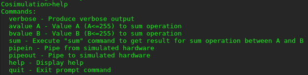
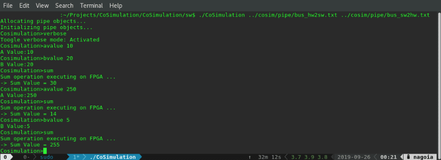
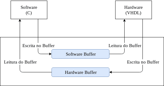
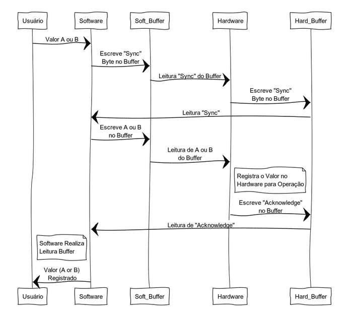
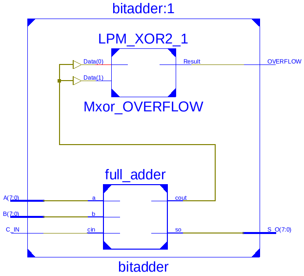
To exemplify the application of co-simulated techinique a 8-Bit Adder will be designed, the hardware (FPGA) is responsible to add two values and the software (microcontroller for instance) is responsible to get the values and pass it to the FPGA. After finish the mathematic operation, the FPGA will retrive the value. All information exchanged between hardware and software is done through buffer files. Bellow, the simplified architecture:
This project is composed by two binary executable files and two files for communication buffer purpose. The binaries are: 1) Generated from a program writen in C language, that has the user interface and; 2) Generated from the simulated hardware, described in VHDL, through the ISim Simulation -Xilinx and it is composed by a 8-bit adder. The buffers are: 1) For writes from the software and reads from the hardware side and; 2) For writes from the hardware and reads from the software.
The information are exchanged by both binaries files is done via a type of file called named pipe or FIFO (First In First Out).
Buffer
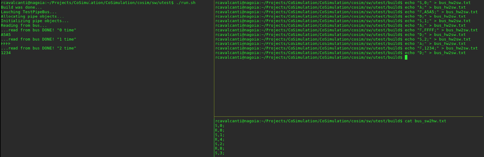
The buffer files will be used here to exchange some information between software and hardware, like a communication channel, as mentioned before. These files are generated automatically in this project after the build through the run.sh script, inside this script the command mkfifo is executed to create the buffers. Bellow, we can see the output for the command ls.

As mainly feature of this files is the behavour to release the memory automatically when a read operation is done. This feature is very useful and a simple test with these files is described below:
Console 1
$ mkfifo test
$ date > test
Console 2
$ cat < test
$ cat < test
Hardware (UUT - Unit Under Test)
Software